
Configuring the parameters for a vehicle profile
In a vehicle profile, you can set the sensors that you want to use.


Procedure

 - Call up the list of vehicles.
- 3.
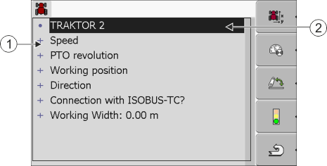
- Select the vehicle profile.
- 4.
- Modify the required parameters. You can also change the name of the vehicle profile.
Parameters in a vehicle profile
Only those parameters which you can use to configure the hardware version of your terminal are shown.
When configuring sensors, you will need not only to select which sensor is mounted, but also how this sensor is connected to the terminal.
This can be done in two ways:
- ▪
- A sensor is connected to the terminal via the serial interface (port B). (e.g.: Operating position sensor, all sensors which can be connected via the 7-pin signal socket). The parameters for the sensors connected in this way do not have the suffix "via CAN".
- ▪
- A sensor is connected to the ISOBUS and its signal reaches the terminal via the CAN interface (port A). The parameters for such sensors always have a "via CAN" suffix.
Speed
Configuring the speed sensor. This measures the speed.
Possible values:
- ▪
- "disabled"
- No sensor measures the speed.
- ▪
- "Wheel sensor"
- A wheel sensor is connected to the terminal. The wheel sensor must be calibrated.
- ▪
- "Radar sensor"
- A radar sensor is connected to the terminal. The radar sensor must be calibrated.
- ▪
- "GPS receiver"
- The speed is calculated using GPS.
- ▪
- "Unknown sensor via CAN"
- A wheel sensor or a radar sensor is connected to the terminal via CAN.
- ▪
- "Radar sensor via CAN"
- A radar sensor is connected to the terminal via CAN.
- ▪
- "Wheel sensor via CAN"
- A wheel sensor is connected to the terminal via CAN.
PTO revolution
Configuring the PTO (power take-off) revolution sensor. This measures the PTO revolutions.
Possible values:
- ▪
- "disabled"
- No sensor measures the PTO revolutions.
- ▪
- "Revol. sensor - front"
- A revolution sensor which is fitted onto the front PTO.
- ▪
- "Revol. sensor - rear"
- A revolution sensor which is fitted onto the rear PTO.
- ▪
- "Impulses/rev."
- Number of impulses which the PTO transfers per revolution.
Working position
With this parameter, you can set whether there is a working position sensor and how its signal reaches the terminal.
Possible values:
- ▪
- "deactivated"
- No sensor measuring the working position.
- ▪
- "Front via connector B"
- A working position sensor, is located on the front hitch or on the implement mounted on the front hitch. It is connected to the terminal via connector B. The working position sensor must be configured.
- ▪
- "Rear via connector B"
- A working position sensor, is located on the rear hitch or on the implement mounted on the front hitch. It is connected to the terminal via connector B. The working position sensor must be configured.
- ▪
- "Unknown sensor via CAN"
- There is a working position sensor determining the working position of the implement. It is connected to an ISOBUS job computer or to a different terminal. The signal reaches the terminal via CAN.
- ▪
- "Front via CAN"
- There is a working position sensor determining the working position of the implement at the front of the vehicle. It is connected to an ISOBUS job computer or to a different terminal. The signal reaches the terminal via CAN.
- ▪
- "Rear via CAN"
- There is a working position sensor determining the working position of the implement at the rear of the vehicle. It is connected to an ISOBUS job computer or to a different terminal. The signal reaches the terminal via CAN.
Direction
You can use these parameters to configure whether the terminal can receive a direction signal, and the source from which it originates. When a direction signal is present, the TRACK-Leader application can correctly mark the vehicle movement when travelling in reverse.
Possible values:
- ▪
- "deactivated"
- No direction sensor is connected to the terminal. If another ISOBUS device transmits a direction signal, however, this is not blocked.
- ▪
- "Unknown sensor via CAN"
- The terminal is receiving a direction signal via CAN whose source is unknown.
- ▪
- "Radar sensor via CAN"
- A radar sensor with direction identification is connected to the terminal via CAN.
- ▪
- "Wheel sensor via CAN"
- A wheel sensor with direction identification is connected to the terminal via CAN.
- ▪
- "Direction sensor"
- A direction sensor is connected to the serial interface of the terminal. Does not function if a working position sensor is connected to the terminal.
- ▪
- "inversion"
- This parameter inverts the meaning of the signals. Only for use with the "Direction sensor" parameter.
Connection with ISOBUS-TC?
With this parameter, you can set whether the Tractor ECU application should communicate with the ISOBUS-TC application. In doing so, it transmits: Counters, working position, position of the GPS receiver.
Deactivate this parameter only if the terminal is used as a secondary terminal and the GPS receiver is connected to a different terminal.
Working width
This value is transmitted to the ISOBUS-TC application to calculate the processed area.
This parameter primarily enables you to document processed areas for non-ISOBUS implements if you are working in TRACK-Leader without an ISOBUS job computer, and if you also use the ISOBUS-TC App simultaneously with ISO-XML tasks.
In this case, no implement data is normally transmitted to ISOBUS-TC. To enable calculation of the processed areas in the Farm Management Information System at a later time, you can enter the working width here.
You can only then use this function if you also have an operating position sensor.
Remember to select a different vehicle profile in the tractor ECU after working with a non-ISOBUS implement, to not always to transfer the working width.
Further information