Parameter
Name
Name of the virtual job computer.
External Controller
If you have connected an on-board integrated display/controller or crop protection sensor to the serial interface, you must select the model in this parameter.
The list contains the following devices:
- ▪
- On-board integrated display/controllers that can communicate using one of the protocols ASD or LH5000 and are capable of communicating with the terminal. If you want to connect an on-board integrated display/controller that supports this protocol, but does not appear in the list, please contact Müller-Elektronik and perform the steps shown at the end of this section.
- ▪
- Crop protection sensors that can be connected to the serial interface of the terminal.
- ▪
- AMABUS. Please note that to connect the AMABUS, you need a special cable, item number: 30322572
Procedure
This is how you update the list of on-board integrated display/controllers:
- þ
- You have contacted Müller-Elektronik and received a USB memory device with the installation file.
- þ
- The Virtual ECU application is closed.
- 1.
- Insert the USB memory device into the terminal.
- 2.
- Start the Virtual ECU application.
- ⇨
- The following message appears: Do you want to update the list of external on-board integrated display/controllers?
- 3.
- Select “Yes” to update the list.
- 4.
- Confirm.
- 5.
- Restart the terminal.
- ⇨
- You can now also select the added on-board integrated display/controller.
Implement type
Use this parameter to define the type of implement.
The following implement types are available:
- ▪
- Seeder
- ▪
- Fertilizer spreader
- ▪
- Sprayer
- ▪
- Soil tillage
Connector type
Use this parameter to define the connector type of the agricultural implement.
The following connector types are possible:
- ▪
- Unknown
- ▪
- Drawbar
- ▪
- 3-point hitch mounted
- ▪
- 3-point hitch semi-mounted
- ▪
- Hitch hook
- ▪
- Clevis coupling
- ▪
- Piton-type coupling
- ▪
- CUNA hitch
- ▪
- Ball-type hitch
Machine model
This parameter influences how the working bar follows the arrow in TRACK-Leader. The configuration improves the precision of the recording of applied areas in curves.
After each change, you also need to adjust the geometry.
Possible values:
- ▪
- “mounted”
- Setting for implements that are mounted on the tractor three-point hitch.
- ▪
- “trailed”
- Settings for implements trailed by a tractor. The working bar is guided like a trailer behind a tractor.
Working width
This parameter shows the working width set for an implement.
Number of sections
Enter the number of sections that can be switched off on the implement. On a field sprayer, they are the section valves; on a fertilizer spreader or a planter/seeder, they can be e.g. metering units.
This parameter serves to transmit the proper number of sections to the SECTION-View module, so that you can switch the sections manually.
Each section appears as part of the working bar on the screen.
Sections
Opens a screen where you can enter the width of the individual sections on the implement.
Geometry
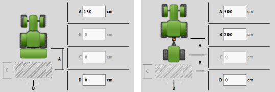
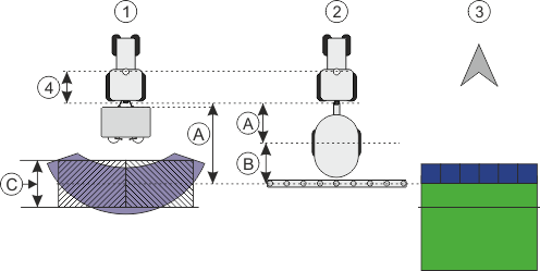
The geometry contains a series of dimensions that help to properly display the vehicle-implement combination in TRACK-Leader and determine its position.
To call up the geometry, tap the function icon:
TRAMLINE-View
TRAMLINE-View contains parameters that are used to correctly display tramlines in TRACK-Leader when using seeders.
To use TRAMLINE-View, the “TRAMLINE-Management” license must be activated.
To call up TRAMLINE-View, tap the function icon:
Parameter:
- ▪
- “Tramline rhythm”
- Defines the tramline rhythm to be used for operation.
- ▪
- “Working Start”
- Defines the point on the field at which you want to start working.
- ▪
- “Begin with half the working width”
- Defines whether you make the first field track after starting to work with only half of the working width.


