Performing diagnostics
In the diagnostic, you can read the measured values for all of the pins that are connected to the junction box. In addition, you can test whether the functions of the job computer are working as desired.
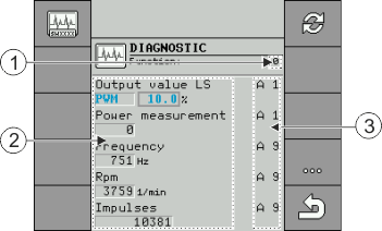
In the diagnostic, you will see the following screen:
The following abbreviations are possible for the cable cores:
- ▪
- "A", "B", "C"
- The designations are analogous to the designations in the assignment plan of the junction box.
Depending on the functions of the individual components, the following measured values are possible:
- ▪
- "Frequency"
- Current measured frequency of the function.
- ▪
- "Rpm"
- Current measured rpm of the function.
- ▪
- "Impulses"
- Current measured number of impulses of the function.
- ▪
- "Analog Value"
- Current measured analog value of the function. The analog value always increases or decreases proportionally.
- Example: The higher the position of an analog work position sensor, the higher the analog value.
- ▪
- "Power Measurement"
- Currently measured current flow of the function. The value of the power measurement always increases or decreases proportionally.
- Example: The faster an electric motor is turning, the higher the value of the power measurement.
- ▪
- "Input"
- –
- "low"
- The function is deactivated. There is no voltage at the input.
- –
- "high"
- The function is activated. There is voltage at the input.
You can enter the following settings:
- ▪
- "Output Value LS"
- –
- "PWM"
- Depending on the entered PWM value, you can test whether an electric or hydraulic motor is turning at the entered PWM value.
- –
- "Rev."
- Depending on the rpm, you can test how long it takes for an electric or hydraulic motor to reach the defined rpm.
- ▪
- "Output Value HS"
- –
- "low"
- The function is deactivated. There is no voltage at the input.
- –
- "high"
- The function is activated. There is voltage at the input.
- ▪
- "Output value HS/LS"
- –
- "low"
- The function is activated or deactivated. Depending on how the function is switched, there either is voltage or not.
- –
- "high"
- –
- The function is activated or deactivated. Depending on how the function is switched, there either is voltage or not.
- ▪
- "Full Bridge"
- With the respective selection, you can test the linear actuators.
- –
- "Stop"
- The function is deactivated. The linear actuator is not moving.
- –
- "+/-"
- The linear actuator is moving in one direction. The direction in which the linear actuator is moving depends on the respective connection.
- –
- "-/+"
- The linear actuator is moving in one direction. The direction in which the linear actuator is moving depends on the respective connection.
Procedure
- þ
- Seeding is stopped.
- ⇨
- The "Diagnostic" screen will appear.
- ⇨
- On the screen, you can see the measured values and possible settings for the individual functions.
Procedure


 >
> 